Unable to make FV-1 work..
Posted: Sat Sep 19, 2015 4:50 pm
Hi all,
After prototyping an effect using the FV-1 devboard, I had designed a PCB layout based off of it, confident that as long as I stick to the rules, it'll work.
My PCBs have come in. Populated the first one, but the FV-1 seemed dead. Checked voltages, tested continuity, caps, everything, and when I was confident that I had indeed kept to the rules, populated a second test PCB this time with the bare minimum the FV-1 would need. The crystal, a few caps and resistors, and the EEPROM. I still get nothing.
Here's the kicker. I get no clock signal on the clock pins on either of my two test boards. If I probe the clock pins on my devboard, I do indeed get the 32KHz clock as expected. The other kicker, the clipping led is constantly on as soon as I power on, even though I keep the input pins floating. That doesn't make any sense.
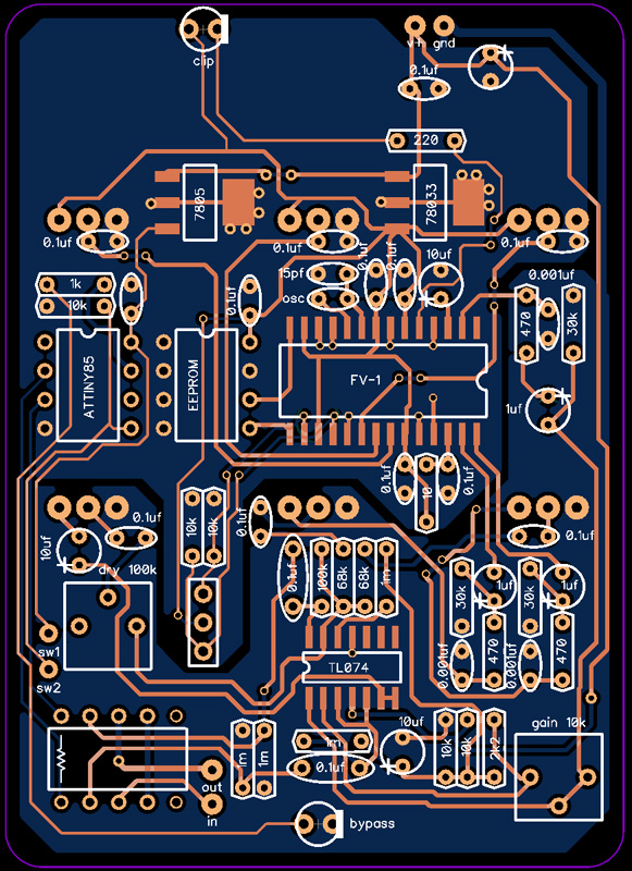
This is my initial layout, the one I thought would work:
http://www.soniccrayonfx.com/private/pi ... er_pcb.jpg
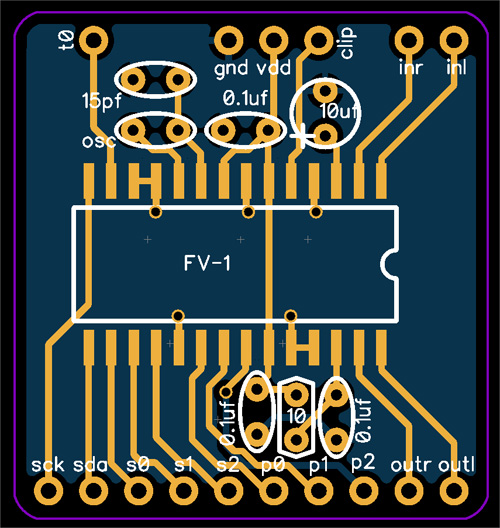
And when that didn't work, I populated only this on a fresh board. Same PCB layout as above, but using only the following components. The minimum that would be needed:
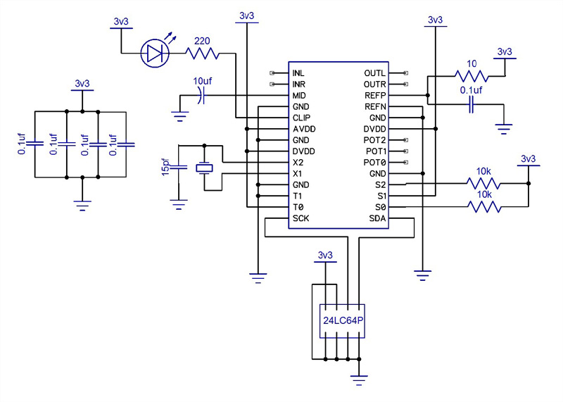
This is exactly how it's hooked up for the official dev board. Decoupling caps as close to the chip as possible, ground fills, etc. I left the inputs/outputs floating as all I needed to confirm was that I could get the FV-1 running, by probing the clock pins. But I don't even have a clock signal. Both chips on both boards just seem dead, and I have no idea why. When I populate only these parts, it's isolated from the rest of the board, so no trouble would come from unpopulated parts of this test board.
I solder quickly and cleanly. I'm used to hand-soldering much finer pitch than this, SOIC is as easy as DIP for me. Not a single shorted pin.
What did I do wrong? I just don't see it!
Voltages are fine, and continuity tests show no shorts and pins are connected to where they're supposed to.
Both the chip and the crystal come from smallbear.
After prototyping an effect using the FV-1 devboard, I had designed a PCB layout based off of it, confident that as long as I stick to the rules, it'll work.
My PCBs have come in. Populated the first one, but the FV-1 seemed dead. Checked voltages, tested continuity, caps, everything, and when I was confident that I had indeed kept to the rules, populated a second test PCB this time with the bare minimum the FV-1 would need. The crystal, a few caps and resistors, and the EEPROM. I still get nothing.
Here's the kicker. I get no clock signal on the clock pins on either of my two test boards. If I probe the clock pins on my devboard, I do indeed get the 32KHz clock as expected. The other kicker, the clipping led is constantly on as soon as I power on, even though I keep the input pins floating. That doesn't make any sense.
This is my initial layout, the one I thought would work:
http://www.soniccrayonfx.com/private/pi ... er_pcb.jpg
And when that didn't work, I populated only this on a fresh board. Same PCB layout as above, but using only the following components. The minimum that would be needed:
This is exactly how it's hooked up for the official dev board. Decoupling caps as close to the chip as possible, ground fills, etc. I left the inputs/outputs floating as all I needed to confirm was that I could get the FV-1 running, by probing the clock pins. But I don't even have a clock signal. Both chips on both boards just seem dead, and I have no idea why. When I populate only these parts, it's isolated from the rest of the board, so no trouble would come from unpopulated parts of this test board.
I solder quickly and cleanly. I'm used to hand-soldering much finer pitch than this, SOIC is as easy as DIP for me. Not a single shorted pin.
What did I do wrong? I just don't see it!
Voltages are fine, and continuity tests show no shorts and pins are connected to where they're supposed to.
Both the chip and the crystal come from smallbear.