Often beginners has no idea how to make program change easy, so this is little snippet to.
It is part of my old AL3201B project
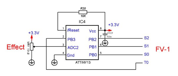
1 potentiometer, 1 MCU Atmel Attiny13.
R20 oftenly not needed, any resistor 1K-20K.
Total budget about $1
Software is pretty dummy
Code: Select all
;************************************************************************
;***           Encoder Emulator v1.2               **********************
;************************************************************************
; by Igor P, nov-2011
;
; PB 0,1,2,3 - out
; pin3 = ADC2 in


; AVR = Z80 Macros
.MACRO di
        cli
.ENDMACRO

.MACRO ei
        sei
.ENDMACRO


.MACRO jc
        brcs @0
.ENDMACRO

.MACRO jnc
        brcc @0
.ENDMACRO

.MACRO jz
        breq @0
.ENDMACRO

.MACRO jnz
        brne @0
.ENDMACRO

.MACRO jr
        rjmp @0
.ENDMACRO

.def		ZERO=r1		;
.def		ADCbase=r2
.def		ADCtemp=r3	;+ что считали с АЦП

.def		temp=r16	;
.def		temp1=r16	;
.def		temp2=r17

.include "tn13def.inc"

		.cseg
		.org 0
		rjmp RESET 	; Reset Handler
	 	reti			; rjmp EXT_INT0 ; IRQ0 Handler
		reti			; PCINT0 Handler
	 	reti 			; Timer0 Overflow Handler
	 	reti			; rjmp EE_RDY 	; EEPROM Ready Handler
	 	reti			; rjmp ANA_COMP ; Analog Comparator Handler
	 	reti			; Timer0 CompareA Handler
	 	reti			; Timer0 CompareB Handler
 		reti			; rjmp WATCHDOG ; Watchdog Interrupt Handler
 		reti  			; ADC Conversion Handler

;***********************************************
;***********************************************
RESET:
;***********************************************
;***********************************************

		di	; Main()

;stack setup

		ldi temp1, low(RAMEND)
		out SPL,temp1 	; Set Stack Pointer to top of RAM

		clr ZERO

;clock scale
		ldi temp, 128+6 ;set clock prescale==64  150kHz
		clr temp2
		out CLKPR,temp
		out CLKPR,temp2 ;скорость 0.15 mhz

; delay if PSU buzzing

		clr temp2
dummy2:
		clr temp1
dummy1:
		dec temp
		nop
		nop
		nop
		nop
		nop
		nop
		jnz dummy1
		dec temp2
		jnz dummy2


;port B bits 0,1,2,3 ==output
		ldi temp1,0b00001111	;
		out DDRB,temp1


;bit 4 - ADC2

;ADC Setup
; no interrups, etc
		ldi temp1, 0b00101111; ain/adc digital inputs off,
		out DIDR0,temp1		;;;;

    	ldi temp1, 0b00100010
    	out ADMUX,temp1; внутр опора, left ajust, channel 2

    	ldi temp1,(1<<ADEN)|(1<<ADSC)|(1<<ADATE)|(0<<ADIF)|(0<<ADIE)|(0<<ADPS0)
		; ADEN = 1 - ADC enable
		; ADIE = 0 no ints
		; ADSC = 1 auto
		; ADATE = 1 continueous
		; ADPS2..0 = 0 - divider 150Khz/2=75 kHz,
		; ADIF - int flag
    	out ADCSRA,temp1
		ei


;   start main prog ;############################################
;============================---- main loop

MainLoop:	rcall delay
		rcall scan_ADCbase
		jr		MainLoop       ;2

scan_ADCbase:
		in 	ADCtemp,ADCH	;1
		cp ADCbase,ADCtemp	;1	;если изменилась база - пересчет
		mov ADCbase,ADCtemp	;1

		jz ScanReturn		; если данные не измеились, ничего не пересчитываем, вываливаемся

		mov temp,ADCbase

		ldi temp2,6		; if (adc < 7) then out_b(6);
		cpi temp,7
		jc ScanFound

		ldi temp2,2		; else if (adc < 39) then out_b(2); ...
		cpi temp,39
		jc ScanFound

		ldi temp2,10		; else if (adc < 68) then out_b(10); ...
		cpi temp,68
		jc ScanFound

		ldi temp2,14
		cpi temp,100
		jc ScanFound

		ldi temp2,15
		cpi temp,128
		jc ScanFound

		ldi temp2,11
		cpi temp,156 ;;;173 ;;;156
		jc ScanFound

		ldi temp2,9
		cpi temp,186
		jc ScanFound

		ldi temp2,13
		cpi temp,215
		jc ScanFound

		ldi temp2,0
		cpi temp,246
		jc ScanFound

		ldi temp2,4	;last
ScanFound:
		out PORTB,temp2
ScanReturn:
		ret

delay:	; Fcpu ~150 kHz. About 50-100 scans per sec, pause needed abut 1500-3000 tacts.

		ldi temp2,4
dly2:
		clr temp1
dly1:
		dec temp
		jnz dly1	;256x3 tacts

		dec temp2
		jnz dly2
		ret
EOP:
;end
"encoder table" is calibrated for 9 effects, but could be reconfigired to 16
(FV-1 ROM and FV-1 external ROM for example)
Compiled with AVR studio or codevision AVR.
I set fuses to 150kHz CPU frequency, to slow down power consumption
Could be flashed via LPT port or cheap programmer like this
https://ru.aliexpress.com/item/1pcs-New ... 87143.html
Next time I can provide another schematic, on STM32F030 to replace both , encoder and i2c EEPROM with one chip