Dirty Encoder Emulator
Posted: Thu Aug 31, 2017 7:31 am
My little contrubution.
Often beginners has no idea how to make program change easy, so this is little snippet to.
It is part of my old AL3201B project
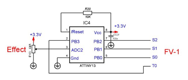
1 potentiometer, 1 MCU Atmel Attiny13.
R20 oftenly not needed, any resistor 1K-20K.
Total budget about $1
Software is pretty dummy
"encoder table" is calibrated for 9 effects, but could be reconfigired to 16
(FV-1 ROM and FV-1 external ROM for example)
Compiled with AVR studio or codevision AVR.
I set fuses to 150kHz CPU frequency, to slow down power consumption
Could be flashed via LPT port or cheap programmer like this
https://ru.aliexpress.com/item/1pcs-New ... 87143.html
Next time I can provide another schematic, on STM32F030 to replace both , encoder and i2c EEPROM with one chip
Often beginners has no idea how to make program change easy, so this is little snippet to.
It is part of my old AL3201B project
1 potentiometer, 1 MCU Atmel Attiny13.
R20 oftenly not needed, any resistor 1K-20K.
Total budget about $1
Software is pretty dummy
Code: Select all
;************************************************************************
;***           Encoder Emulator v1.2               **********************
;************************************************************************
; by Igor P, nov-2011
;
; PB 0,1,2,3 - out
; pin3 = ADC2 in


; AVR = Z80 Macros
.MACRO di
        cli
.ENDMACRO

.MACRO ei
        sei
.ENDMACRO


.MACRO jc
        brcs @0
.ENDMACRO

.MACRO jnc
        brcc @0
.ENDMACRO

.MACRO jz
        breq @0
.ENDMACRO

.MACRO jnz
        brne @0
.ENDMACRO

.MACRO jr
        rjmp @0
.ENDMACRO

.def		ZERO=r1		;
.def		ADCbase=r2
.def		ADCtemp=r3	;+ что считали с АЦП

.def		temp=r16	;
.def		temp1=r16	;
.def		temp2=r17

.include "tn13def.inc"

		.cseg
		.org 0
		rjmp RESET 	; Reset Handler
	 	reti			; rjmp EXT_INT0 ; IRQ0 Handler
		reti			; PCINT0 Handler
	 	reti 			; Timer0 Overflow Handler
	 	reti			; rjmp EE_RDY 	; EEPROM Ready Handler
	 	reti			; rjmp ANA_COMP ; Analog Comparator Handler
	 	reti			; Timer0 CompareA Handler
	 	reti			; Timer0 CompareB Handler
 		reti			; rjmp WATCHDOG ; Watchdog Interrupt Handler
 		reti  			; ADC Conversion Handler

;***********************************************
;***********************************************
RESET:
;***********************************************
;***********************************************

		di	; Main()

;stack setup

		ldi temp1, low(RAMEND)
		out SPL,temp1 	; Set Stack Pointer to top of RAM

		clr ZERO

;clock scale
		ldi temp, 128+6 ;set clock prescale==64  150kHz
		clr temp2
		out CLKPR,temp
		out CLKPR,temp2 ;скорость 0.15 mhz

; delay if PSU buzzing

		clr temp2
dummy2:
		clr temp1
dummy1:
		dec temp
		nop
		nop
		nop
		nop
		nop
		nop
		jnz dummy1
		dec temp2
		jnz dummy2


;port B bits 0,1,2,3 ==output
		ldi temp1,0b00001111	;
		out DDRB,temp1


;bit 4 - ADC2

;ADC Setup
; no interrups, etc
		ldi temp1, 0b00101111; ain/adc digital inputs off,
		out DIDR0,temp1		;;;;

    	ldi temp1, 0b00100010
    	out ADMUX,temp1; внутр опора, left ajust, channel 2

    	ldi temp1,(1<<ADEN)|(1<<ADSC)|(1<<ADATE)|(0<<ADIF)|(0<<ADIE)|(0<<ADPS0)
		; ADEN = 1 - ADC enable
		; ADIE = 0 no ints
		; ADSC = 1 auto
		; ADATE = 1 continueous
		; ADPS2..0 = 0 - divider 150Khz/2=75 kHz,
		; ADIF - int flag
    	out ADCSRA,temp1
		ei


;   start main prog ;############################################
;============================---- main loop

MainLoop:	rcall delay
		rcall scan_ADCbase
		jr		MainLoop       ;2

scan_ADCbase:
		in 	ADCtemp,ADCH	;1
		cp ADCbase,ADCtemp	;1	;если изменилась база - пересчет
		mov ADCbase,ADCtemp	;1

		jz ScanReturn		; если данные не измеились, ничего не пересчитываем, вываливаемся

		mov temp,ADCbase

		ldi temp2,6		; if (adc < 7) then out_b(6);
		cpi temp,7
		jc ScanFound

		ldi temp2,2		; else if (adc < 39) then out_b(2); ...
		cpi temp,39
		jc ScanFound

		ldi temp2,10		; else if (adc < 68) then out_b(10); ...
		cpi temp,68
		jc ScanFound

		ldi temp2,14
		cpi temp,100
		jc ScanFound

		ldi temp2,15
		cpi temp,128
		jc ScanFound

		ldi temp2,11
		cpi temp,156 ;;;173 ;;;156
		jc ScanFound

		ldi temp2,9
		cpi temp,186
		jc ScanFound

		ldi temp2,13
		cpi temp,215
		jc ScanFound

		ldi temp2,0
		cpi temp,246
		jc ScanFound

		ldi temp2,4	;last
ScanFound:
		out PORTB,temp2
ScanReturn:
		ret

delay:	; Fcpu ~150 kHz. About 50-100 scans per sec, pause needed abut 1500-3000 tacts.

		ldi temp2,4
dly2:
		clr temp1
dly1:
		dec temp
		jnz dly1	;256x3 tacts

		dec temp2
		jnz dly2
		ret
EOP:
;end
"encoder table" is calibrated for 9 effects, but could be reconfigired to 16
(FV-1 ROM and FV-1 external ROM for example)
Compiled with AVR studio or codevision AVR.
I set fuses to 150kHz CPU frequency, to slow down power consumption
Could be flashed via LPT port or cheap programmer like this
https://ru.aliexpress.com/item/1pcs-New ... 87143.html
Next time I can provide another schematic, on STM32F030 to replace both , encoder and i2c EEPROM with one chip