Page 1 of 1
Eeprom switch bck1001
Posted: Sat Nov 03, 2018 2:29 am
by leetut
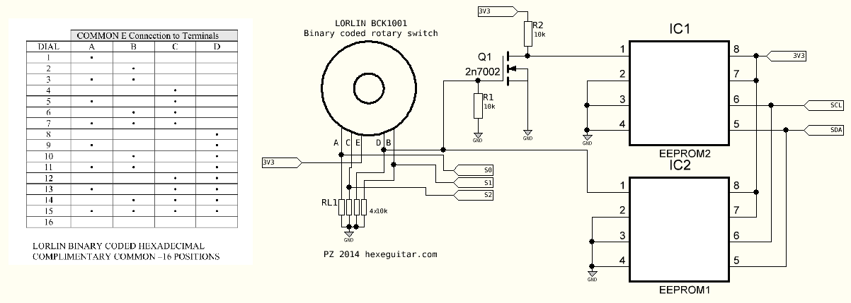
Hi, about the below bck1001 switch schematic, it takes me 4 turns/clicks to get the next program, and only loads 2 programs /repeated, so 4 programs in total, any ideas what I could be doing wrong?
Re: Eeprom switch bck1001
Posted: Sun Nov 04, 2018 11:15 am
by ice-nine
I see that you are swapping between EEproms by switching power to pin pin1, the best way is to change state of one of the address line pins. that may work better.
Re: Eeprom switch bck1001
Posted: Thu Nov 22, 2018 8:26 am
by leetut
http://www.pedalpcb.com/docs/Octagon.pdf
This is the schematic of the circuit I’m trying to add the rotary switch to, after removing the attiny85 nothing else seems to be connected to s0 s1 s2 but the mode pot still affects the rotary switch somehow, mode pot needs to be fully ccw to get the above behavior (4 turns to select a program)
If it turn the mode pot clockwise the rotary switch won’t work at all,
Tried removing the mode pot but the rotary switch wouldn’t work again
Just to clarify, I’m trying to remove the mode pot that selects between 8 programs via the attiny85,
And replace it with the rotary switch circuit
Re: Eeprom switch bck1001
Posted: Thu Nov 22, 2018 4:03 pm
by ice-nine
leetut wrote: ↑Thu Nov 22, 2018 8:26 am
http://www.pedalpcb.com/docs/Octagon.pdf
This is the schematic of the circuit I’m trying to add the rotary switch to, after removing the attiny85 nothing else seems to be connected to s0 s1 s2 but the mode pot still affects the rotary switch somehow, mode pot needs to be fully ccw to get the above behavior (4 turns to select a program)
If it turn the mode pot clockwise the rotary switch won’t work at all,
Tried removing the mode pot but the rotary switch wouldn’t work again
Just to clarify, I’m trying to remove the mode pot that selects between 8 programs via the attiny85,
And replace it with the rotary switch circuit
Best way would be leave the atiny in place and replace the pot with the 8 way rotary switch with resistor ladder to control the control the atiny. Simplest and most effective way. The other way is remove the atiny and use the switch with diodes to make it a 3 bit selector for S0-S2
Re: Eeprom switch bck1001
Posted: Thu Nov 22, 2018 4:24 pm
by leetut
It’s a 16 position rotary switch not 8, and I don’t think I can connect it where the mode pot is, it has 5 lugs A B C D E and the mode pot only has 3
Re: Eeprom switch bck1001
Posted: Thu Nov 22, 2018 4:46 pm
by ice-nine
leetut wrote: ↑Thu Nov 22, 2018 4:24 pm
It’s a 16 position rotary switch not 8, and I don’t think I can connect it where the mode pot is, it has 5 lugs A B C D E and the mode pot only has 3
Ok, that is not a switch as such,it is a 4 bit grey code binary encoder. Take a look at the SpinSemi docs for similar configs, you will be able to replace the entire Atiny chip and wire that encoder to the S0-S2 pins of the FV-1. If it is a grey code encoder you will have to place your programs in the order of the you want them to match the encoder output. see the encoders datasheet for output .
Here is a similar encoder setup [urlhttp://
www.spinsemi.com/app_download/3K_SKE.pdf][/url] you would need to wire yours according to the datasheet of your switch.
Re: Eeprom switch bck1001
Posted: Thu Nov 22, 2018 5:30 pm
by leetut
But it doesn’t work, that’s why I’m here!
Re: Eeprom switch bck1001
Posted: Fri Nov 23, 2018 3:21 pm
by ice-nine
leetut wrote: ↑Thu Nov 22, 2018 5:30 pm
But it doesn’t work, that’s why I’m here!
In that case, I would suggest you wire the encoded up on breadboard using LED's on the output and note down the truth table when each LED illuminates, check that the encoder is actually working correctly as per the data sheet. If the encoder is working correctly then you will need to look at how you have the EEPROM and the S0-S2 wire up. Have you programmed the EEPOMS with 8 programs each ?
Re: Eeprom switch bck1001
Posted: Sun Nov 25, 2018 4:23 am
by leetut
I’m afraid I just have to accept defeat with this one, thank you for the info and advice anyway
Re: Eeprom switch bck1001
Posted: Sun Dec 02, 2018 11:04 am
by leetut
Update: I wasn’t even going into s0 s1 s2, worked perfectly when I figured that out

Re: Eeprom switch bck1001
Posted: Sun Dec 02, 2018 4:34 pm
by ice-nine
leetut wrote: ↑Sun Dec 02, 2018 11:04 am
Update: I wasn’t even going into s0 s1 s2, worked perfectly when I figured that out
Glad you got it figured out, although I don't get that you never connected to S0-S2 in the first place??
Re: Eeprom switch bck1001
Posted: Tue Dec 04, 2018 5:12 am
by leetut
My point of access is the 8 pin socket that holds the attiny, it’s connected to the fv1 but it’s upside down on the schematic, so pins 5 6 7 are connected to s0 s1 s2, but on the pcb it looks like pins 1 2 3
Re: Eeprom switch bck1001
Posted: Tue Jan 01, 2019 5:07 am
by leetut
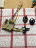
Finally got this working with the lorlin 16 position switch, thanks for the tips!

Re: Eeprom switch bck1001
Posted: Sun Jan 10, 2021 7:51 pm
by tomsouthtrader
Glad to hear you got it working! And your board looks great.

Though I am wondering what the third IC on the board is? Assuming the others are the two EEPROMs you are switching between..
How did you deviate from the original schematic?
And are there any differences in how you are coding your proms to make it work?
Many Thanks!
Tom.
