Page 1 of 1
Sin/Cos LFO
Posted: Thu Aug 30, 2012 7:45 am
by gfisys
Hi Frank, I've been looking around the website and found this example code :
http://www.spinsemi.com/knowledge_base/pitch_sft.html
In that example I noticed that instead of simply using the LFO output the code actually computes the cos and sin values as depicted by the SIN/COS LFO block diagram (
http://www.spinsemi.com/knowledge_base/arch.html).
Is there a specific reason for doing that?
Posted: Thu Aug 30, 2012 9:16 am
by frank
Yes, the shift frequency is greater than can be generated by the LFO block in the chip so we had to generate the sin and cos in the code.
Posted: Thu Aug 30, 2012 12:18 pm
by Sweetalk
I'm trying to use the SIN0 to make an LFO and put it on the DACL. I looked on the knowledge base to read directly the sin generator and put it on the ACC to later write on the DAC but doesn't work at all. Something like this:
Code: Select all
cho	rdal,		sin0		;Read LFO SIN0
wrax	dacl,		0		;Write to DACL.
Initialized like this, and rate controlled by POT2
Code: Select all
skp	run,		2
wlds	sin0,	10,	800
clr

rdax	pot2,		1		;Read POT2
mulx	pot2				;Multiply by itself to get more logaritmic taper
sof	0.02,		0.01		;Escale 1Hz to 3Hz
wrax	sin0_rate,	0		;Write on rate register of SIN0
Quote from the CHO instruction explanation:
cho rdal,sin1 ;load accumulator with SIN/COS1 LFO output (Sine only)
There's something that I'm missing or what I'm doing wrong?.
Posted: Thu Aug 30, 2012 1:16 pm
by frank
The code looks OK but 2 things jump out:
1. Your amplitude is really small at 800, make it 8000
2. Look directly at the pin of the FV-1, your signal only goes 1Hz - 3Hz and any caps will greatly attenuate the signal if you are looking at the jack on a dev board (or any board if you are looking after DC blocking caps).
Doing the above (setting amp to 8000 and looking at the pin on the FV-1) I saw the sin wave on the left DAC output.
Posted: Thu Aug 30, 2012 1:53 pm
by Sweetalk
frank wrote:The code looks OK but 2 things jump out:
1. Your amplitude is really small at 800, make it 8000
2. Look directly at the pin of the FV-1, your signal only goes 1Hz - 3Hz and any caps will greatly attenuate the signal if you are looking at the jack on a dev board (or any board if you are looking after DC blocking caps).
Doing the above (setting amp to 8000 and looking at the pin on the FV-1) I saw the sin wave on the left DAC output.
The 800 was putted on the second try, but I started with 32767 as in the knowledge base says that's the max amplitude.
I have no caps, directly to the pin
Posted: Thu Aug 30, 2012 4:28 pm
by frank
This is the code I tried and it worked:
Code: Select all
skp   run,      2
wlds   sin0,   10,   8000
clr

rdax   pot2,      1      ;Read POT2
mulx   pot2            ;Multiply by itself to get more logaritmic taper
sof   0.02,      0.01      ;Escale 1Hz to 3Hz
wrax   sin0_rate,   0      ;Write on rate register of SIN0

cho   rdal,      sin0      ;Read LFO SIN0
wrax   dacl,      0      ;Write to DACL.
I do see the sin wave on the left output, I am using a digital scope and have input coupling set to DC (not AC, that may filter out the 1 - 3 Hz signal depending on scope).
Posted: Fri Aug 31, 2012 3:57 am
by gfisys
frank wrote:Yes, the shift frequency is greater than can be generated by the LFO block in the chip so we had to generate the sin and cos in the code.
Ah I see, so the variable you used in that code to specify the oscillator frequency for generating the sin/cos has different meaning than the one you would use with WLDS instruction or when writting to the LFO's rate register?
What's the formula should I use to come up with the correct 'rate' value to do sin/cos generation? Let's say I'd like to generate a 40 Hz sin/cos, what 'rate' value would I feed the sin/cos LFO block diagram with?
Sweetalk wrote:frank wrote:The code looks OK but 2 things jump out:
1. Your amplitude is really small at 800, make it 8000
2. Look directly at the pin of the FV-1, your signal only goes 1Hz - 3Hz and any caps will greatly attenuate the signal if you are looking at the jack on a dev board (or any board if you are looking after DC blocking caps).
Doing the above (setting amp to 8000 and looking at the pin on the FV-1) I saw the sin wave on the left DAC output.
The 800 was putted on the second try, but I started with 32767 as in the knowledge base says that's the max amplitude.
I have no caps, directly to the pin
Try configuring your scope's input for 'DC Coupling' as Frank did, that would ensure the 1Hz-3Hz signal is properly captured by the scope. You may need to adjust the vertical resolution or vertical position of the display to bring the waveform into view since the output signal would be biased at around 1.65V instead of 0V.
Posted: Fri Aug 31, 2012 9:04 am
by frank
gfisys wrote:
Ah I see, so the variable you used in that code to specify the oscillator frequency for generating the sin/cos has different meaning than the one you would use with WLDS instruction or when writting to the LFO's rate register?
Yes, they are different due to certain things in the hardware versus doing it in software.
gfisys wrote:
What's the formula should I use to come up with the correct 'rate' value to do sin/cos generation? Let's say I'd like to generate a 40 Hz sin/cos, what 'rate' value would I feed the sin/cos LFO block diagram with?
See
http://www.spinsemi.com/Products/appnot ... N-0001.pdf for the equations for the LFO block, note it is limited to about 20Hz so for 40Hz you will probably need to do it in s/w.
Posted: Fri Aug 31, 2012 8:09 pm
by gfisys
frank wrote:gfisys wrote:
Ah I see, so the variable you used in that code to specify the oscillator frequency for generating the sin/cos has different meaning than the one you would use with WLDS instruction or when writting to the LFO's rate register?
Yes, they are different due to certain things in the hardware versus doing it in software.
gfisys wrote:
What's the formula should I use to come up with the correct 'rate' value to do sin/cos generation? Let's say I'd like to generate a 40 Hz sin/cos, what 'rate' value would I feed the sin/cos LFO block diagram with?
See
http://www.spinsemi.com/Products/appnot ... N-0001.pdf for the equations for the LFO block, note it is limited to about 20Hz so for 40Hz you will probably need to do it in s/w.
By 'doing it in software' you mean manually computing the sin/cos values right? How do I translate the frequency that I want (in Hz) into the quantity 'rate' with which I would compute the sin/cos values in software?
For example, the pitch-shifter code does this :
Code: Select all
rdax cososc,1    ; read COS reg
mulx shift       ; multiply by shift control value
rdax sinosc,1    ; add SIN reg
wrax sinosc,-1   ; write SIN reg, invert phase
mulx shift      ; multiply by shift control value
rdax cososc,1   ; add COS reg
wrax cososc,0   ; write COS reg, clear ACC
The above code computes the sin/cos values as per the block diagram below, and the quantity 'shift' in that code corresponds to the quantity 'RATE' in that block diagram :
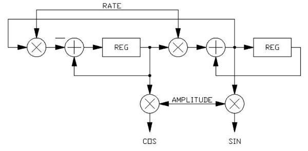
My question is, for a given frequency X Hz, how do I calculate the quantity 'shift' for that piece of code (equivalently, the 'RATE' in that block diagram)? I can't use the equation in
http://www.spinsemi.com/Products/appnot ... N-0001.pdf since it's intended for use with WLDS instruction right?
Posted: Sun Sep 02, 2012 11:01 am
by frank
I don't recall the equations, been a while since I coded one of these but it is based on a trig identity and is a rather popular method to generate sine waves so a google search should find the answer. They should be similar to the ones in the app note but not identical.
Posted: Sun Jun 02, 2013 9:52 pm
by Digital Larry
An article which talks about DSP oscillators is here:
http://www.ied.com/~petr/Oscillators.html#Complex Oscillator
Not sure which one applies to the FV-1's approach.